Внимание! Сайт переехал на новый адрес: http://zpostbox.ru/u2_e.htm


Miscellaneous circuits - part 2

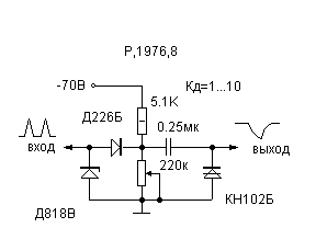
1. Schmitt trigger circuit diagram.

Schmitt trigger circuit diagram

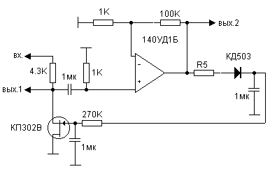
2. Audio compressor.

Audio compressor circuit diagram

3. Comparator with level-dependent hysteresis.
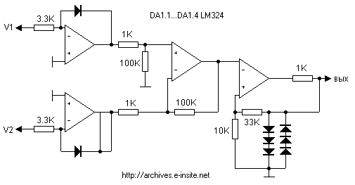
Comparator with level-dependent hysteresis circuit diagram

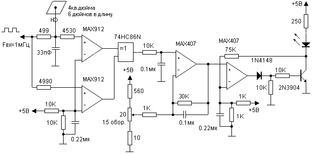
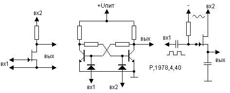
4. Capacitive sensor.

Capacitive sensor circuit diagram

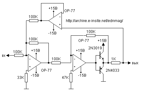
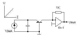
5. Voltage to current converter.

Voltage to current converter circuit schematic

6. Bridge with current stabilisation circuit.
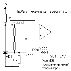
Bridge with current stabilisation circuit diagram

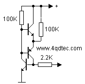
7. Two-terminal circuit with negative resistance.
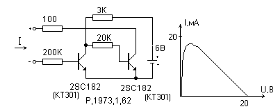
Two-terminal circuit with negative resistance

8. Window comparator circuit diagram.
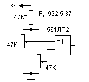
Window comparator circuit diagram

9. Phase detector circui.

Phase detector circuit schematic

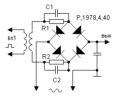
10. Switch mode phase detectors.

Switch mode phase detectors

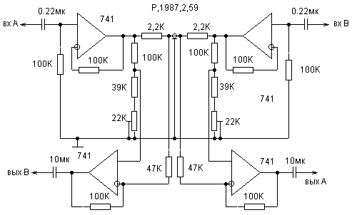
11. Balanced phase detector circuit diagram.
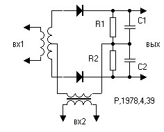
Balanced phase detector circuit diagram

12. High Input Impedance AC Amplifier.
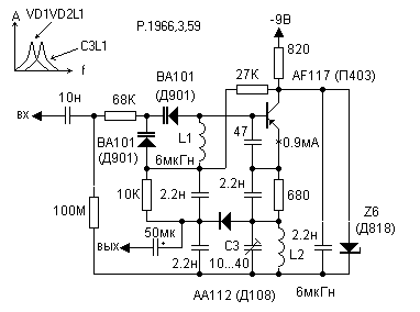
High Input Impedance AC Amplifier circuit schematic

13. Trigger based on opto-isolator circuit schematic.
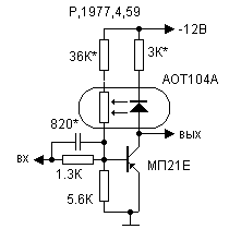
Trigger based on opto-isolator circuit diagram

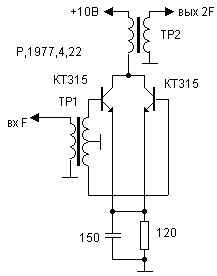
14. Frequency doubler.

Frequency doubler circuit schematic

15. Stepper motor controller based on IC 7474 circuit schematic.
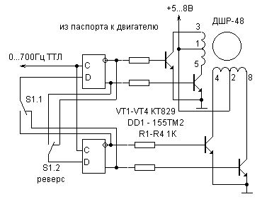
Stepper motor controller circuit schematic

16. Stepper motor working in synchronous mode.
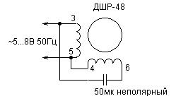
Stepper motor working in synchronous mode circuit schematic

17. Triangular wave to sine wave converter.
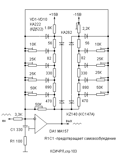
triangular to sine converter circuit diagram

18. Bidirectional intercom circuit.

Two-sided transmission line circuit diagram

19. Frequency divider with variable division ratio.
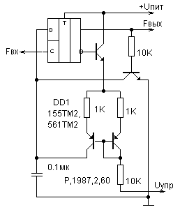
Frequency divider with variable coefficient of dividing

20. Sawtooth wave to sine wave converter circuit.
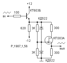
Sawtooth to sine converter circuit schematic

21. Changing band of variable capacitor by transformer.
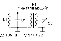
Changing band of variable capacitor by transformer

22. Welding transformer circuit diagram.
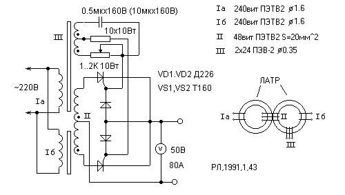
Welding transformer circuit diagram

23. Metal detector circuit.

Metal detector circuit diagram

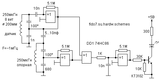
24. Superregenerative metal detector circuit.
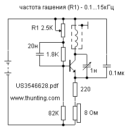
Superregenerative metal detector circuit diagram

25. Sensitive capacitive sensor circuit.
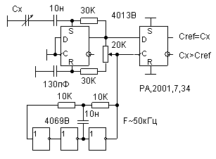
Sensitive capacitive sensor circuit diagram

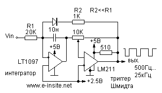
26. Voltage to frequency converter.

Voltage to frequency converter circuit schematic

27. Regenerative capacitance multiplier.
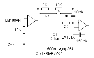
Regenerative capacitance multiplier circuit

28. Equalization of output resistance.
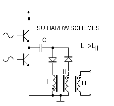
Equalization of output resistance circuit diagram

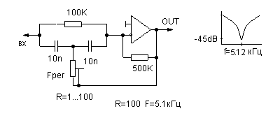
29. Wien bridge notch filter circuit schematic.
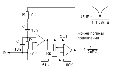
Wien bridge notch filter circuit schematic

30. Compensate capacity load to avoid self-excitation.
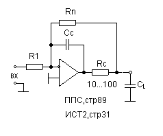
Compensate capacity load to avoid self-excitation

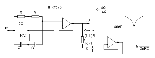
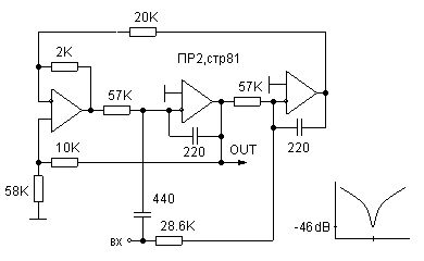
31. Notch filter circuit.

Notch filter circuit diagram

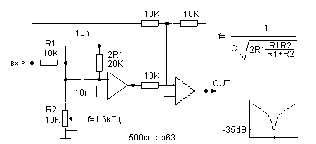
32. Notch filter based double T-shaped bridge circuit.
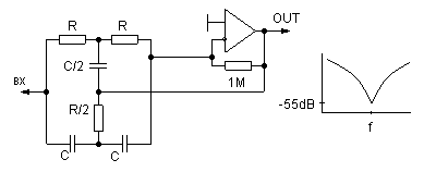
Notch filter based double T-shaped bridge circuit diagram

33. Adjustable notch filter circuit based on bridge differential unit.
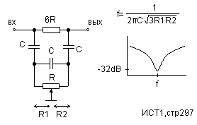
Adjustable notch filter circuit based on bridge differential unit circuit diagram

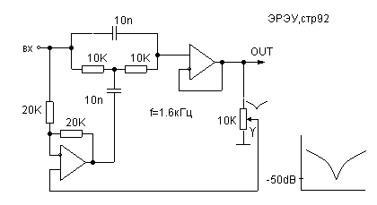
34. Notch filter circuit.

Notch filter circuit schematic

35. Active notch filter circuit.

Active notch filter circuit diagram

36. Notch filter circuit with Wien-Robinson bridge.
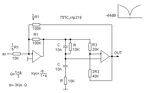
Notch filter circuit with Wien-Robinson bridge circuit diagram

37. Notch filter circuit.

Notch filter circuit schematic

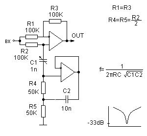
38. Adjustable notch filter circuit.

Adjustable notch filter circuit diagram

39. Adjustable notch filter circuit.

Adjustable notch filter circuit schematic

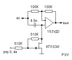
40. Variable capacitor based on Op-Am.
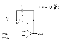
Variable capacitor based on Op-Amp circuit diagram

41. Phase modulator based on op-amp.

Phase modulator circuit diagram

42. Increasing amplitude of single pulse.
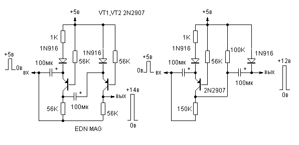
Increasing amplitude of single pulse circuit diagram

43. Equivalent of resistor with high resistance.
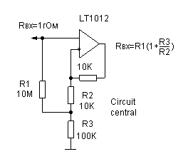
Equivalent of resistor with high resistance circuit diagram

44. Resonant filter based on rejection filter.
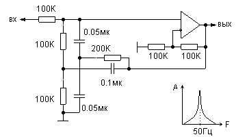
Resonant filter based on rejection filter circuit diagram

45. Resistance to period converter circuit.
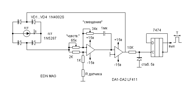
Resistance to period converter circuit diagram

46. Sine wave to sawtooth wave converter.
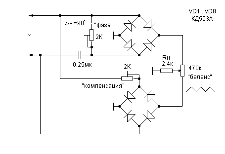
Sawtooth former from sine signal circuit diagram

47. Frequency divider based on DIAC.

Frequency divider based on DIAC circuit diagram

48. Nonlinear sawtooth wave to sine wave converter.
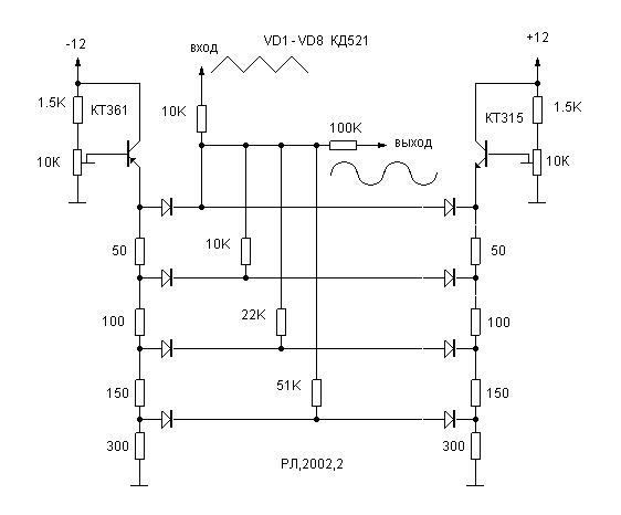
Nonlinear sawtooth to sine converter circuit diagram

49. Sine wave former circuit diagram.
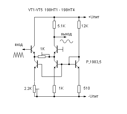
Sine wave former circuit diagram

50. Regenerative notch filter circuit.
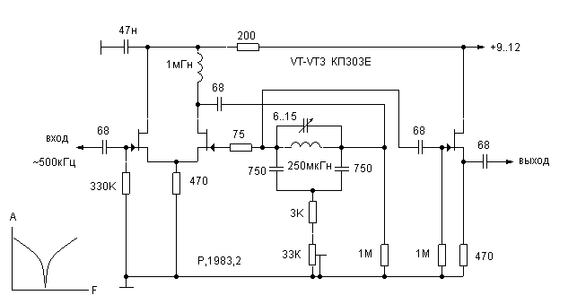
Regenerative notch filter circuit diagram

51. Replacement of the high-resistance feedback resistor on a low resistance.
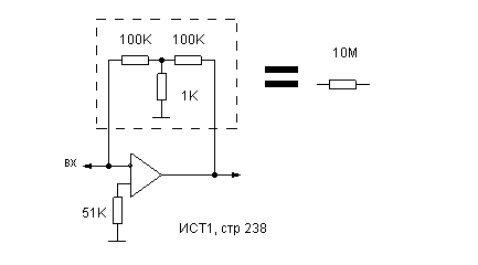
Replacement of the high-resistance feedback on a low resistance

52. Sawtooth wave to sine wave converter circuit.
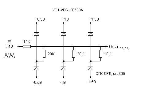
Sawtooth wave to sine wave converter circuit diagram

53. Voltage to current converter.

Voltage to current converter circuit schematic

54. Neutralization feedthrough capacitance.
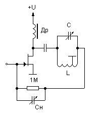
Neutralization feedthrough capacitance circuit

55. Regenerative frequency divider circuit.
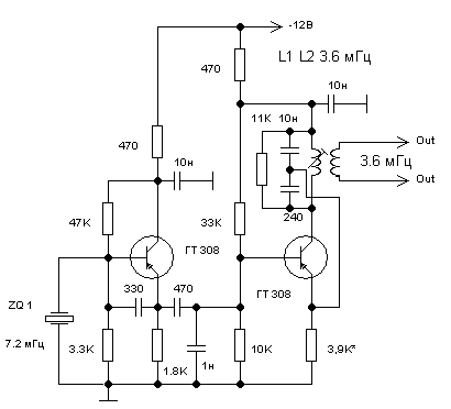
Regenerative frequency divider circuit diagram

PREV НОМЕ

Хостинг от uCoz