Digital Signal Generators
Radio 1986, 4
The most common way of producing a signals of different waveforms is using a digital methods to synthesize it. This allows to get high stability of frequency, phase and amplitude of the signal. The generators, described below can generats sinusoidal and sawtooth signals that may be used in measurement and other circuits.
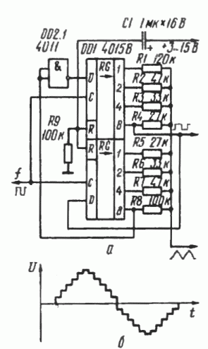
The circuit shown in figure 1, generates oscillations with waveforms identical to sine wave signal. If change the value of resistors R1-R8 then could be achieved other form of the output signal.

Fig. 1. C1 - 1μF, 16V
After applying power supply, the network R9C1 produces a short pulse that sets all the bits of the eight-bit shift register DD1 in zero state. As a result, the inverting output of the gate DD2.1 is high, and so, the data input "D" of the upper (in the schematic diagram) register DD1 has high level too. The clock frequency of an oscillator goes to the clock inputs "C" of the shift register. With each of the rising edge of the clock pulses the data in the register are shifted by one bit, and the register are filling up with high level bits until the input of the gate DD2.1 gets high level. Now the data input "D" of the upper register DD1 has low logic level and the shift register will be filled with zero bits. This process will repeat over and over again while the circuit is powered.
The digital-analog converter (DAC) consists of the resistors R1-R8, the DAC converts the digital code that circulating in the register into the sine wave with the frequency of 1/16 of the clock oscillator frequency. Since CMOS ICs can operate at frequencies no more than 7 MHz, the maximum output frequency of the sinusoidal signal is about 0.5 MHz, the form of the generated signal is shown in Fig. 1b. The most significant harmonics are the third and the fifth and they have a level of -50 dB relative to the first harmonic. The intensity of the 15th and 17th harmonics is much higher, but they can be easily filtered out by using a simple RC-filter.
The circuit also produces square waves with the same frequency and phase as the sine wave. It can be used, for example, to synchronize an oscilloscope.

Fig. 2.
The circuit shown in figure 2a, produces a step voltage similar to sinusoidal wave, this generator can be used in a voltage converter circuits, in a remote control radio equipment, and in generators to power the motors. It consists of a binary counter modulo-3, based on a flip-flops of the IC DD1, and DAC, which consists of only two resistors. Output frequency of the generator is equal to 1/3 of input frequency. The figure 2b clearly explains the process of forming a sinusoidal signal out of the square signal.

Fig. 3.
The figure 3 shows the circuit of the digital sawtooth voltage generator, which can be used as a sweep generator of a curve tracer. The device contains the 14-bit binary counter and the 8-bit linear DAC, which consists of the resistors R1-R24. This DAC provides a stepwise increase of the output voltage with a step equal to 1/256 of the amplitude of the generated signals, which is about 1/5 of the power supply voltage. The generator also produces a square wave signal (with frequency f/214), its trailing edge corresponds with the beginning of the formation of the sawtooth voltage. The frequency of the stepwise output voltage at a constant amplitude can be varied in a wide range by changing the input frequency. The generator can be especially useful in cases where the period of the sawtooth voltage is long enough (minutes and hours), when it cannot be easily achieved with analog techniques.
Sources:
- Digital Sinewave Generator, - Elektor (GB), 1980, № 7, p. 16-17.
- Oscillatore Sinusoidale Digitale. - Elektor (It), 1982, M 38/39 (July-Aug.), p. 52. 1
- J. Mejer. Digital Logarithmic sweep generator. - Elektor (GB), 1982. № 7/8 (luly/Aug), p. 67